IGBT modules are often used in a variety of high-power power supplies and large-power motor drivers. Their high power increases the operating voltage, so operating voltages around 1,000V are not uncommon. Due to the time sequence separation of each IGBT, the operating bias voltage between its gate and emitter is provided by an independent isolating transformer. When this transformer is in operation, there will be high-frequency and high-voltage PWM switching between the primary and secondary sides (see Figure 1). Many users and manufacturers have insufficient understanding of the difference between the breakdown voltage of the wire itself and the partial discharge inception voltage (PDIV) among the wires. This is why common transformers often fail to carry out correct insulation, correct insulation design, and production testing. In turn, it damages the IGBT or triggers all kinds of abnormal actions on the digital side due to high-voltage discharge surges.
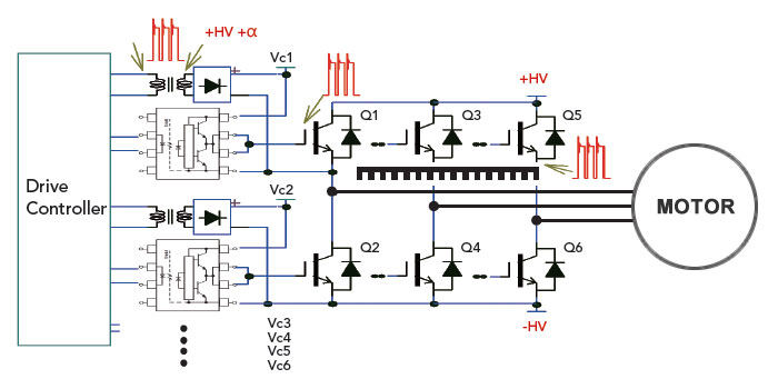
▲Figure 1 – Motor Drive Control Circuit Diagram
If the voltage difference between the primary and secondary sides of the transformer is a square wave with a peak voltage of 1,000V, the non-certified quality requirements generally are designed to withstand voltage >2,000V. Then, using a wire with a breakdown voltage >3,000V to wind on both sides of the wire, even if it is adjacent, it can withstand 6,000V, right?
The answer is that it may be able to withstand 6,000V for a minute, but still could fail after a period of actual work (1,000V square wave). The reason is that the permittivity of regular insulation is much higher than that of air, resulting in a higher proportion of partial pressure in the air under AC conditions. The partial pressure of the air between the lines reaches >350V_peak (1atm gas short-distance discharge inception voltage), continuing the partial discharge (PD) and gradually carbonizing until short-circuited (refer to Figure 2). Or, even before the transformer is destroyed, the PD surge is likely to cause abnormal interference on the digital circuit to malfunction eventually.

▲Figure 2 –Continuous Corona Discharge Leading to Transformer Coil Short Circuit between Primary and Secondary Sides
Figure 3 shows an example of malfunctioning caused by a high-power IGBT control transformer. The abnormal transformer clearly emits light due to corona discharge during use, although the transformer was not judged abnormal in the general part test or in the power supply final product test. However, during actual use, malfunctions or abnormalities in the IGBT module or digital system often result in quality issues that are not easy to identify, even requiring the replacement or design optimization of the transformer.

▲Figure 3 –Continuous Corona Discharge Malfunctioning in High Power IGBT Control Transformer
Normally, the transformer industry only conducts withstand voltage testing according to specifications, and does not test for PD or flashover. Consequently, such issues occur widely in electrical and electronic products used in various power supplies. To avoid PD or flashover problems, you must ensure that there is no continuous PD under its working conditions. Relevant regulations (e.g. IEC60747-5-5) generally suggest that 1.875 times the highest possible use potential should be tested in production (for a few seconds) without PD (e.g. PD <15pC) to ensure long-term product quality. Take a peak of 1,000V as an example, about 1.325kVrms @ 60Hz (1.875kV_peak), PD <15pC may be a suitable detection. (Please note that the measured partial discharge inception voltage of the transformer in this application example is only about 400Vac, which is far below the expected quality capacity.)
Chroma 19501 series provide AC withstand voltage test (10kVac) and partial discharge test (1pC~2,000pC). The best solution for PD abnormality detection in high-voltage products, these testers oversee lasting quality and reliability of your products.

▲Figure 4 – Chroma 19501-K Partial Discharge Tester
In addition, use the Chroma 11890 Programmable HF AC Tester (5kVrms / 100mA / 10kHz~200kHz) for abnormal acceleration tests (PD degradation speed is approximately proportional to frequency) to verify defective spots and design improvements.
Please visit the Chroma website to learn more about the functions and specifications of Chroma 19501 Partial Discharge Tester or of Chroma 11890 Programmable HF AC Tester:
| Partial Discharge Tester Model 19501-K |
| Programmable HF AC Tester Model 11890 |