


The Chroma 19301A Impulse Winding Tester combines high & low inductance test technologies, has a maximum impulse voltage of 1000V, and a high speed sampling rate of 200MHz which satisfies most of the test requirements for power inductor products with a wide inductance range from 0.1uH to 1mH. The built-in functions of Area Size Comparison, Differential Area Comparison, FLUTTER Value, LAPLACIAN Value, ΔPEAK or Δ PEAK RATIO, PEAK RATIO and ΔRESONANT AREA functions are able to inspect coils for poor insulation effectively.
The inspection of wound components for production includes the electrical characteristics test and the withstand voltage test of the electrical safety standard. Poor insulation of a coil, which is a common issue that causes layer short and/or short circuit with the output pin during use, can be caused by bad design, bad molding process, or deterioration of the insulation material. Therefore, it is necessary to perform the layer short test on any winding component or coil.
The 19301A, which is specifically designed for wound component tests, utilizes a high voltage & low capacitance capacitor (low test energy) in parallel with a coil to form an RLC resonant, which is called damping. Analyzing the decay of the waveform via an analysis technology with high speed, precise, and accurate sampling can successfully detect poor insulation within a coil. It provides the winding quality test and the withstand voltage test on the cores for power inductors, and also makes the manufacturer and user checks of the quality of winding component products more efficient.
The 19301A can be used to test low inductance winding components with a minimum inductance down to 0.1uH. It provides 4-terminal (4-wire) measurement, contact checks, inductance check and voltage compensation for testing low inductance winding components in order to avoid gross inaccuracies in test voltage caused by the inductance variation of the DUT or the equivalent inductance of wires, which makes it the best impulse winding test instrument for low inductance winding components.
The 19301A has an extremely high test speed that can reduce testing times and increase productivity in automated production. In addition, the voltage compensation function reduces the impac t of the equivalent inductance of the wiring in automated machines.
The brand new Human Machine Interface has a colorful display and screen capture function. The screenshot of the waveform, which is not only suitable for the on-site production but also applicable for R&D and Quality Assurance to analyze and compare, can be saved through the USB port on the front side of the instrument. This improves the convenience of operation.
Measurement Technology
Introduction & Theory of Impulse Test
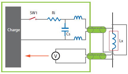
The "impulse winding test" applies a "non-destructive", high speed and low energy impulse voltage to a DUT. The capacitor (Cs) and the wound component are parallel to form an RLC circuit that generates RLC resonance when an impulse voltage is applied to the RLC circuit. By observing the decay of its oscillations, which is also called damping, we can understand the manufacturing process status of the wound component including the insulation, the inductance, and the parallel equivalent capacitance (Cw) (as shown in Figure 1: Diagram of equivalent circuit test). Either good or defective products can also be identified by analyzing and comparing their test waveforms. The main purpose of the impulse winding test is to find potential defects in wound components as early as possible, examples include a layer short between wires, poor welding (lack of fusion), and poor insulation on the internal coil or core.

▲ Figure 1: Equivalent Circuit

▲ Figure 2 : WV Test
Rp Check
The Peak Ratio and the Δ Peak or Δ Peak Ratio are unique testing technologies from Chroma. Before performing any tests, a large core loss or a short circuit between the core and enamel insulated wire of wound components can cause the Q values to drop (smaller Rp).
Under the breakdown voltage (BDV) test mode, the Peak Ratio can be used to detect the changes of the parallel resistance (Rp) of the DUT for inspecting the abnormality or deterioration of the Rp. After the withstand voltage test is done and the switch is opened (SW1 OFF), it calculates the Peak Ratio from the measurement, which is the ratio of the 2nd peak value to the 1st peak value of the oscillatory voltage waveform. As the voltage increases continuously, the Peak Ratio can inspect the changes of the Rp that are caused by the abnormality or deterioration in order to find the breakdown voltage (BDV) or the deterioration voltage (DTR.V). The larger Peak Ratio indicates the greater Rp value, which also means the higher Q value.
Under the impulse winding test (IWT) mode, the Δ Peak or Δ Peak Ratio can be used for detecting defective products by comparing the Peak Ratio from the test product with a known good product. After the withstand voltage test is done and the switch is opened (SW1 OFF), it uses the Peak Ratios from the DUT and the sample to calculate the Δ Peak or Δ Peak Ratio, which is the difference of the Peak Ratio between the DUT and the sample or the difference of the Peak Ratio between the DUT and the sample in the decay ratio from the sample for identifying defective products.

▲ Figure 3: WV Test & Peak Ratio Waveform
Waveform Judgment Mode
Area Size: This function compares the total area size of the sampled waveform with the test waveform of the DUT. The area size is affected by the insulation of a coil. Poor insulation of a coil causes the waveform to decay rapidly, which results in an area size smaller than the reference.
Differential Area: This function uses point to point comparison to calculate the differential area, which is the area created between a sample waveform and the test waveform from the DUT. The result of the differential area test is relevant to the inductance difference between the sample and the DUT. The difference in inductance causes the oscillation frequency to be different, and creates the differential area between the sample waveform and the test waveform. The larger the difference of the inductance, the larger the differential area created.
Flutter Detection: This function uses the first derivative to calculate the Flutter value, which represents the sum of the slopes from the waveform. It compares the Flutter value from the DUT with the Flutter value from the sample to determine whether discharge has occurred on/in the DUT. When discharge has occurred during the test, the Flutter value from the DUT is larger than the value from the sample.
Laplacian Value: This function uses the second derivative to calculate the Laplacian value, which represents the rate of the changing slope or the curvature/concavity of the waveform. When the value is positive, the curve is concave up. When the value is negative, the curve is concave down. It then compares the Laplacian value from the DUT with the Laplacian value from the sample, which can effectively detect rapid changes in the waveform caused by electrical discharge or poor electrode welding.

▲ Figure 4: Area Size

▲ Figure 5: Differential Area

▲ Figure 6: Flutter and Laplacian for Discharge Waveform
Peak Ratio: Under the BDV test mode, the 19301A calculates the Peak Ratio of the 2nd peak value to the 1st peak value by using the 1st and 2nd amplitude of the resonant waveform from the DUT. It also utilizes the allowance range to judge whether the DUT is excessively deteriorated by increasing the test voltage. This can also be used to analyze the deterioration voltage / breakdown voltage of a DUT.


▲ Figure 7: Peak Ratio
ΔPeak /ΔPeak Ratio: Under the IWT test mode, the 19301A compares the Peak Ratio of the resonant waveform from the DUT and the sample in order to calculate the ΔPeak or ΔPeak Ratio. If the Peak Ratios from the DUT to the sample are the same, theΔPeak or ΔPeak Ratio will be equal to 0%. The ΔPeak is the difference in Peak Ratio between the DUT and the sample. The ΔPeak Ratio is the difference in the Peak Ratio between the DUT and the sample divided by the decay ratio from the sample. The operator can use the high and low limits of the ΔPeak or ΔPeak Ratio to set the permissible range for sorting out defective products that have a significant difference from the sample.

ΔResonant Area: Under the IWT test mode, after the switch is opened (SW1 OFF), the 19301A compares the total area of the resonant waveform from the DUT with the sample, similar to the Area Size function. The size of the resonant area is relevant to the insulation of a coil. Poor insulation of a coil causes the waveform to decay rapidly, which causes the resonant area to be smaller than the sample, well-insulated coil.

▲ Figure 8: Resonant Area
Low Inductance Impulse Test Technology
The Chroma 19301A is specifically developed for testing low inductance wound components. The layer short test can be applied to wound components that have a minimum inductance of 0.1uH. The test for a DUT with low inductance is different from general inductance products. Because of the low inductance, the DUT is easily affected by the equivalent inductance from the wiring of the test circuit, which causes the test voltage to be distributed across the test circuit, making the actual test voltage on the DUT much lower than the set voltage. Moreover, the operating voltage of a power choke with low inductance is low, thus the impulse test voltage is generally lower than general inductance products.
Low Voltage Range
Low inductance products such as power chokes inside smartphones have a low operating voltage and smaller volume, so test voltage is relatively low. Therefore, the impulse test equipment for testing low inductance products needs to have a low voltage range to analyze the waveform. Chroma 19301A has seven voltage ranges: 25V, 50V, 100V, 200V, 400V, 800V and 1000V. The lowest voltage resolution of 0.06V, and minimum test voltage of 10V, improves the capability for waveform identification.

▲ Figure 9: Chroma 19301A Impulse Winding Tester

▲ Figure 10: Common Impulse Tester
4-Terminal Measurement
The voltage meter/sensor of common 2-wire layer short test equipment is inside the current loop for measuring voltage, creating a big difference between the measured voltage and the actual voltage on the DUT. The Chroma 19301A uses dual coaxial 4-wire detection, which is also called 4-Terminal Measurement, to substantially improve voltage accuracy for more accurate test results.
▲ Figure 11: 4-Terminal Measurement Diagram
Contact Check (Patent: I516773)
The Chroma 19301A performs a Contact Check, which can extend the service life of the fixture or probe, before the test in order to avoid poor contact or open circuits that would cause the 19301A to generate a high voltage output, preventing arcing to the fixture or probe and damage to the DUT.
Voltage Compensation (Patent: I516773)
Voltage Compensation (Patent: I516773)
In general tests of high inductance wound components such as transformers, the effect of the equivalent inductance of the wiring is relatively small. However, in testing wound components with low inductance (such as 0.2uH), the actual test voltage on the DUT can be easily affected by the equivalent inductance of the wiring. Reducing the impact of the wiring is a major design concern, especially in automated testing. When the impedance of the wiring is too great, the test voltage is distributed to the wire, which causes the actual test voltage on the DUT to become much lower than the set voltage, and the inspection for defective products to become ineffective.
Moreover, the tolerance of the inductance specified for the wound component can be ±30%. Therefore the difference in actual test voltage, caused by the differential inductance from the DUT, is even more obvious in low inductance wound component tests. This can cause the Area Size function to become invalid or the test voltage to fail the requirement. The Chroma 19301A features a voltage compensation function for differential inductance, which resolves the above problems and reduces the difference of the actual test voltage caused by differential inductance in order to reduce the possibility of misjudgment.
In general, the DUT with inductance (Lx) is in series with the equivalent inductance (Li & Lw) of the wiring in the test circuit, which divides the output voltage (V). The voltage (Vx) across the DUT is smaller than the output voltage (V). The equivalent formula to calculate the voltage (Vx) across the DUT is shown below.


▲ Figure 12: Equivalent Circuit for Voltage Compensation

▲ Figure 13: Without Compensation Voltage

▲ Figure 14: With Compensation Voltage
Application
High & Low Inductance Products Test
The 19301A not only has low inductance product test technology but also covers high inductance product tests. It is able to test products with inductance values from 0.1uH to 1mH.When the sample is measured for inductance, the 19301A automatically switches to the proper range according to the measurement for the sample and test. This waveform sample is then used to compare with the DUT to verify that the DUT has the proper waveform. This is a very convenient function for the operator. Combining the applications of the high & low inductance test technologies into a single layer short tester not only reduces changeover time on the production line helping production management, but also reduces the cost of facility/equipment for the factory.
B.D.V - Breakdown Voltage
The 19301A has breakdown voltage analysis built in. The start voltage, end voltage, and percentage between each step can be set under the breakdown voltage (BDV) test mode. While the test voltage increases in each step, it can use Area Size, Laplacian, and Peak ratio functions to judge whether the result from each function is over the specified limit in order to find the withstand voltage of the test coil. In addition, it can also use the Deterioration Detection function to find the deterioration voltage (DTR.V). R&D engineers can analyze and research the product and improve any weaknesses of a coil design by using these functions under BDV test mode.
Deterioration Point Analysis
Under BDV test mode, the 19301A utilizes the changes in Peak Ratio to detect whether the DUT starts to deteriorate. When the DUT starts to deteriorate, the Peak Ratio decreases. The continuous decay times of the Peak Ratio, which can be set from 3 to 5 times, can be used to detect the deterioration voltage (DTR.V) of a DUT.

▲ Figure 15: Deterioration Detection
Pause
Under BDV test mode, the Pause function can be enabled by the operator. This function causes the 19301A to perform the test one step at a time each time the [START] key is pressed. The test is paused after each test step is done until the [START] key has been pressed again to begin the next step. This function can be used by the operator when it is necessary to move the DUT for other analysis or tests between each step, and return to continue the BDV test at the next step.

▲ Figure 16: Pause Function and Screenshot
Screenshot
This function allows the operator to capture the current screen display by pressing the shortcut keys. The captured screen display is saved to a USB flash drive plugged in the 19301A.
Export Data
This function exports the current test result and saves it to a USB flash drive plugged in the 19301A. This allows the operator to analyze the data of each test result. The format of the data file is CSV (Comma Separated Values).
High Speed Automated Testing Application
The low inductance products are used in smart-phones, tablet PCs, etc., so the size of the inductor trends toward smaller, thinner and lighter. Fully automated test and packing machines, which have a high production speed, are used in producing these inductors. Therefore, high speed test equipment is required to satisfy the high speed of production. The Chroma 19301A provides high speed tests and uses dual coaxial 4-wire detection (4-Terminal Measurement) to reduce the impact of wiring length, which can work perfectly with automated machines for layer tests in order to provide greater benefit for customers. The shortest length of time for the high speed test has been improved to 20mS, which can considerably improve the quantity of automated production output.
SMA Power Choke Test Fixture
The size of a low inductance Power Choke is quite small. Chroma has developed a 4-Terminal measurement fixture (patent), which can work with the voltage compensation by inductance difference, specifically for the SMD Power Choke in order to facilitate the operation of the layer short test and to improve test efficiency for the R&D engineer, the product developer, and the QA staff.

▲ Figure 17: SMD Power Choke Test Fixture (A193001)


